


A circuit is a drawing of connected wires, cables, clamps, connectors, which are parts of an electrical circuit. A distinction is made between series, parallel and combined connections.
Features of a series electrical circuit
A simple design looks like this: one lamp is connected to the power supply, a second lamp is connected to it, then the wire is connected to the circuit breaker (key) and the remaining wire is connected to the battery. A chain of components is formed, where each element is mandatory. And if something stops working, the rest of the chain becomes inactive.

The features are the same current strength at each point of energy consumption. If the voltage is constant, the current value is corrected by changing the resistance.
Rtotal = I1 = I2 = In
U = U1 + U2 + Un
U = I*R1 + I*R2 + I*Rn
In this type of circuit, the current remains constant in any section and the total resistance is the sum of the values of the constituent components. The sum of the voltage drops is equal to the line voltage according to Ohm’s law.
Voltage divider
In the literature on radio electronics you can meet such a concept as “voltage divider“. It is a closed electrical circuit made of 2 or more elements.
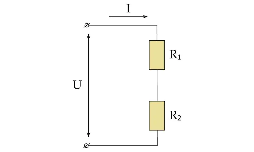
In such a simple circuit, you can see that there are 2 resistors in the circuit. Therefore, the current value can be found by this formula:
I = U : (R1 + R2)
U2 = I*R2
I = U : (R1 + R2)
UR2 = U*R2 : (R1 + R2) – for the second resistor
UR1 = U*R1 : (R1 + R2) – for the first resistor
Now we prove that the voltage in the circuit is equal to the sum of the voltage drops across both resistors:
U = UR1 + UR2 = U*R1 : (R1 + R2) / U*R2 : (R1 + R2) = U* (R1 + R2) / (R1 + R2) = U
According to Kirchhoff’s law, in a series circuit, if there is a closed loop, the sum of the voltages will be zero.
U = U1 + U2;
U – U1 – U2 = 0.
An example of a series circuit is a simple Christmas tree light. As soon as one element burns out, it becomes impossible for current to flow through the wires and the other bulbs are switched off.
Features of a parallel circuit
In a closed circuit of a lamp, the conductors are connected in such a way that the ends and beginnings are respectively connected at the same point (phase). Electricity will flow through the circuit in different paths. The number of conductors can be from 1-2 pieces to hundreds of units. The voltage values for each element are equal, but the current will be different.

U = U1 = U2 = Un
I = I1 + I2 + In
U = I*R1 + I*R2 + I*Rn
According to Ohm’s law: I = U : R
IR1 = U : R1, IR2 = U : R2, IR3 = U : R3
U / R = U / R1 + U / R2 + U / R3
Dividing the expression by U, we obtain:
1 / R = 1 / R1 + 1 / R2 + 1 / R3
We conclude that the inverse value of the total resistance consists of the sum of the inverse values of the resistances of each conductor.
This expression can be visualized in another way. Let’s simplify it by taking a circuit of 2 conductors:
R = 1 : (1 / R1 + 1 / R2) = 1 : {(R2 + R1) / R1*R2} = R1*R2 / R2 + R1.
In the special case where the resistance of each of a pair of conductors is equal, we arrive at this formula:
R total = R1*R2 / R2 + R1 = R2 / 2 = 0,5 R2,
that is, the total resistance of two conductors in a network with equal values of individual resistances is equal to half of the square of the value of R.
Kirchhoff’s law looks different for a parallel circuit than for a series circuit:
I = I1 + I2 + In
I – I1 – I2 – In = 0
The total value of the currents in the circuit is zero.
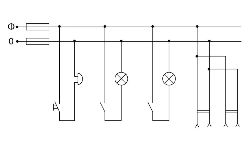
Parallel connection is more common than series connection. An example is any living room with many electrical appliances. They are each activated in their own mode, they can be switched off, and the network will continue to operate for other energy consumers. The figure shows that the neutral wire, to which the objects are activated, is grounded. And the phase line connects all the switches in a separate line.
Combined connection of conductors in a circuit
The components are connected to each other in a parallel circuit and connected in series to the resistor. To calculate the total resistance of the circuit, it is necessary to separately determine the values for the different connection circuits. The first calculations are made in the series circuit.
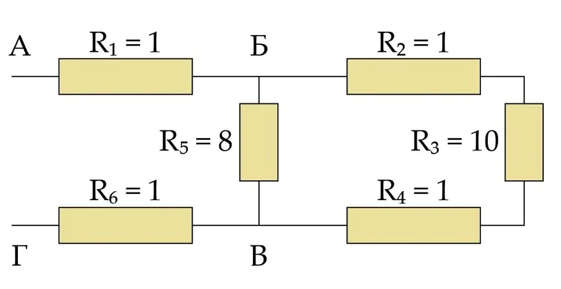
The calculation of such circuits is subject to Kirchhoff’s second law. It states: when there is a closed circuit, the sum of generated EMFs is equal in value to the sum of voltage drops.
If we look at an example, we get this solution:

E1-E2 = I*R1 + I*R2
For the calculation, it is important to calculate the algebraic sum because the co-directional EMF and the opposite directional currents have different mathematical signs when the voltages drop.
E1-E2 – algebraic sum of EMF
I*R1 + I*R2 – voltage drop.
E1-E2 = I*R1 + I*R2
I = (E1 – E2) / (R + R1 + R2)
Comparison of results for two circuit modeling schemes
Let’s take a look at the main differences between electrical circuits assembled taking into account the basic element wiring diagrams.
Electrical connection in series
Advantages
- The circuit has a very simple design: easy to draw, quick to assemble.
- It is allowed to use devices whose voltage is lower than the nominal mains potential.
- The same current is applied to each device.
- Moderate cost of completing the circuit.
Disadvantages
- Decrease in voltage when the connected energy consumers increase.
- If one of the devices in the circuit breaks down, the other devices will not work as well.
Parallel electrical connection
Advantages
- Connecting and disconnecting devices does not affect the other current consumers in the circuit.
- If one element of the circuit is not working, the other elements continue to function as before.
- It is possible to connect devices with different current strengths – voltage will be supplied to all at once.
Disadvantages
- It is forbidden to connect equipment to the network, in which the voltage value during operation is lower than the network voltage.
- It will take longer to design the circuit, and its realization in practice will cost more.
The series solution is suitable for the use of toggle switches and switches. It is used in case of creating a circuit of devices with low operating voltage. When it is necessary, for example, to reduce the total capacitance of the devices, a series connection is used to reduce the value by half.
How to install measuring instruments in the circuit to be created
Quite often it is necessary to add measuring devices to the experimental circuit: an ammeter to display the actual current measurement and a voltmeter to determine the voltage value. What is the correct way to do this?
An ammeter is placed in series with the workload in the circuit. Parallel inclusion will lead to failure of the measuring instrument. The resistance value should be very small, so as not to interfere with the devices.
The situation is different with a voltmeter. The device must have a large resistance value. Then you can ignore the current that is consumed by the device. When connected, it is placed in parallel with what generates electricity or consumes it.