


Almost any type of heater, even if it is designed for a current of 220 V, can have several types of connection that differ from each other in the number of phases: one-, two- and three-phase. In this case, there are several connection schemes that will be discussed in this article.
Single phase connection
This is the simplest way to connect an electric heater to a power source. A phase is supplied to the first conductor connected to the heating element core, the second one acts as a neutral (“zero”, through which the current returns). A typical example of a single-phase connection is shown in Img. 1.

This type of connection is most common in household power networks with a voltage of 220-240 V, as well as other networks, the voltage of which is from 12 to 60 V (in 12 V steps), as well as 110 V. In Fig. 2 schematically shows the connection to a single-phase source.


There is no polarity in electric heaters, so the phase (voltage) can be applied to either of the two conductors. This feature determines the key advantages of this type of connection: versatility and simplicity.
Two-phase connection
This type of connection also involves only two conductors connected to the electric heater. However, instead of “zero”, a second phase is supplied to the second conductor. Neutral is not provided in this type of connection. An example of a two-phase connection can be seen in the figure below.

This type of connection is used on 380 to 400 V AC power networks. It does not involve any visual or structural changes compared to a single-phase connection, as can be seen by looking at the diagram in IMG 4.


A two-phase connection has its advantages and disadvantages. The heating element generates thermal energy of greater power. However, the increase in power negatively affects the operational life and reliability of the heating element.
Three-phase connection
There are two options for implementing this type of connection: “star” and “triangle”. Both schemes are illustrated in the figure below.


There is one difference between the indicated three-phase connection schemes related to voltage: the supply of phase 220 V or linear 380 V. Regardless of the choice of connection scheme, the phase current remains constant.
The star connection option is shown in the figure below.

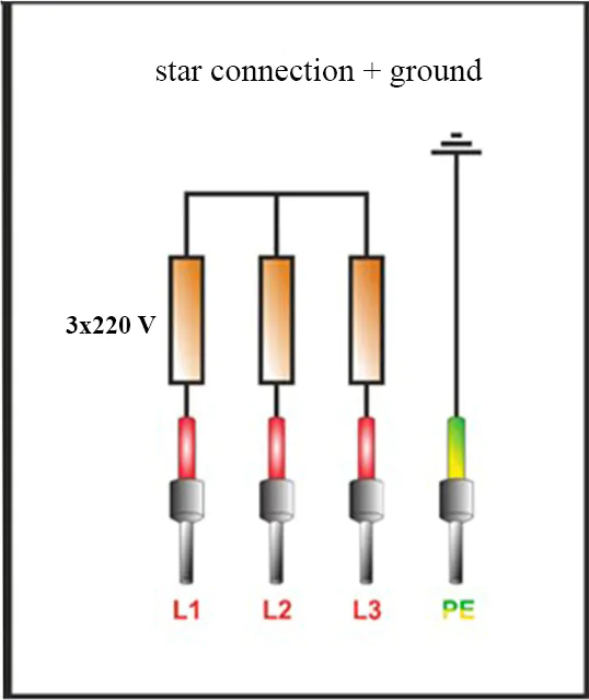
To implement this connection scheme, three conductors are used, including zero, which is usually highlighted in blue. In some circuits, the presence of a neutral conductor is not provided. But this option for implementing a three-phase connection is highly discouraged (a zero contact must be present).
The principle of connecting the heating element to the power source according to the “star” scheme is shown in the figure below.


The manufacturer can complete his product with contacts instead of wires. As a rule, zero contacts are always marked in blue, as shown in the figure below.
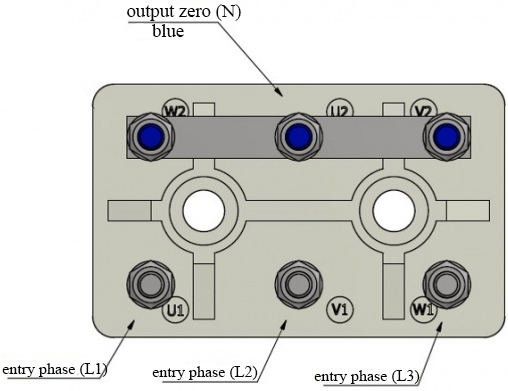
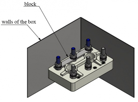
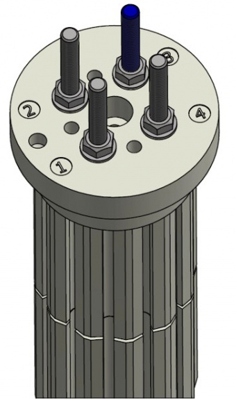

Three-phase connection has two important advantages over other types of connection: higher reliability and longer service life. This is due to two features: the use of phase voltage (220-240 V) and the presence of a resistor having a large cross-sectional area. The only drawback of this type of connection is the loss in power. However, you can achieve higher power in a three-phase type of connection using the second circuit – the “triangle” (shown schematically in the figure below).

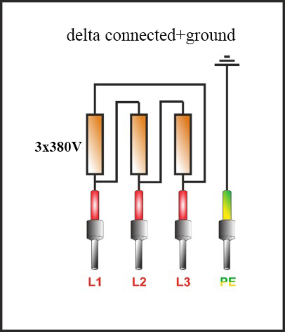
This connection scheme is used when working with a linear voltage of about 380 V. At the same time, two phases are supplied to each section of the heater circuit, which is the main difference from the previous connection scheme, in which only one phase was supplied to each section.
In this scheme (it is customary to call it “classical”), three conductors are involved, to which three phases are supplied. In this circuit, there is no neutral conductor. The figures below clearly demonstrate the principles of connection using the “classic” scheme.

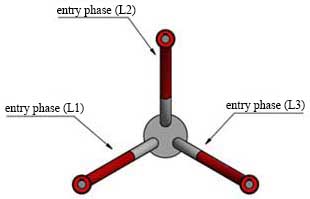

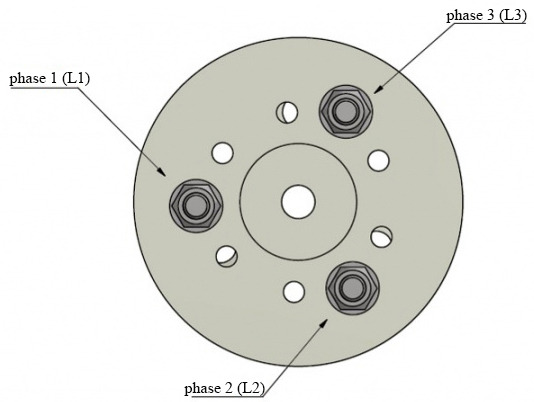
This connection option has two important advantages compared to the star connection: higher power, easy connection, and no extra conductors. Like any type of connection, the “classic” circuit has a drawback – a reduced resource of the heating element due to the high current power.
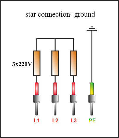
The circuit contains protective grounding for safety purposes, as well as grounding, which is necessary for potential equalization. Many mistakenly consider these two concepts to be identical.
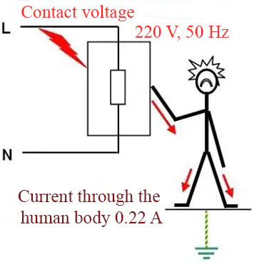
To avoid accidents, the connected equipment must be grounded initially (these are the requirements of safety regulations). Heating elements that are not made in metal cases do not require grounding. The need for grounding to prevent accidents is clearly illustrated in the figure below.

The following figures show various connection schemes with a ground wire.

Thermocouple in heating elements
Heating elements contain a thermocouple, which is designed to determine the temperature of the heater itself, and not the object to which it transfers thermal energy. Two types of thermoelectric converters are commonly used:
“K” – a thin conductor covered with white insulation.
“J” – a conductor with a metal braid and color insulation.
If it is impossible to establish the type of conductor by its external characteristics, it is recommended to use their magnetic properties. A “K” type thermocouple will have a magnetized negative wire, while a “J” type thermocouple will have a positive wire magnetized.
Thermocouple connection options are indicated in the figures below.


When connecting TPM, use the diagram shown on the device case. The supply phase and zero are connected to the first two ports. The phase and the heating element are connected to the third and fourth ports. The plus and minus of the thermal sensor are connected to the 13th and 14th ports, respectively.

Connection options are shown in the figures below.


For more information about the types and connection diagrams of electric heaters, please contact the experts. Three important parameters depend on the chosen option: power, reliability and operational period.